Popular Keywords
3D Packaging
News

[News] Equipment Manufacturers’ Global Race for Hybrid Bonding Opportunities
Global semiconductor giants are concentrating their R&D efforts on advanced packaging technologies to drive performance enhancements. According to a report from Commercial Times, as packaging technology progresses from 2.5D to 3D, chip stacking technologies have become a showcase for the competi...
Press Releases

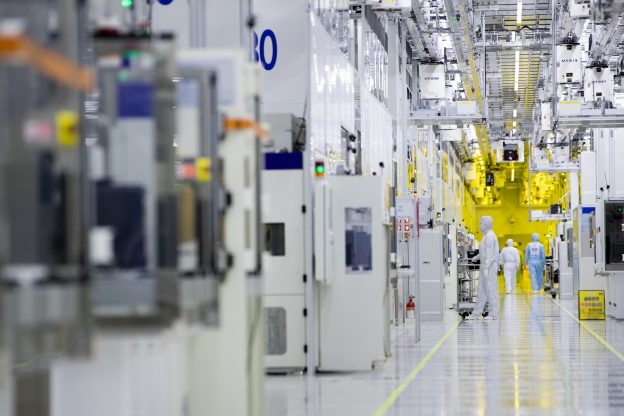
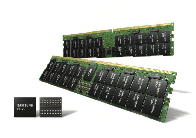
[News] Samsung Plans to Introduce 3D HBM Chip Packaging Service in 2024
In 2023, Samsung disclosed plans to launch its advanced three-dimensional (3D) chip packaging technology, which would be able to integrate memory and processors needed for high-performance chips, in much smaller sizes. Now, at the Samsung Foundry Forum in San Jose taken place in June, the tech giant...
Insights

[News] Understanding 3DIC, Heterogeneous Integration, SiP, and Chiplets at Once
The semiconductor industry enters the era of integration. Various foundries are focusing on advanced packaging technologies, but the terminology surrounding advanced packaging can be daunting. This article aims to explain these terms in the simplest way possible. According to a report from TechNe...
In-Depth Analyses

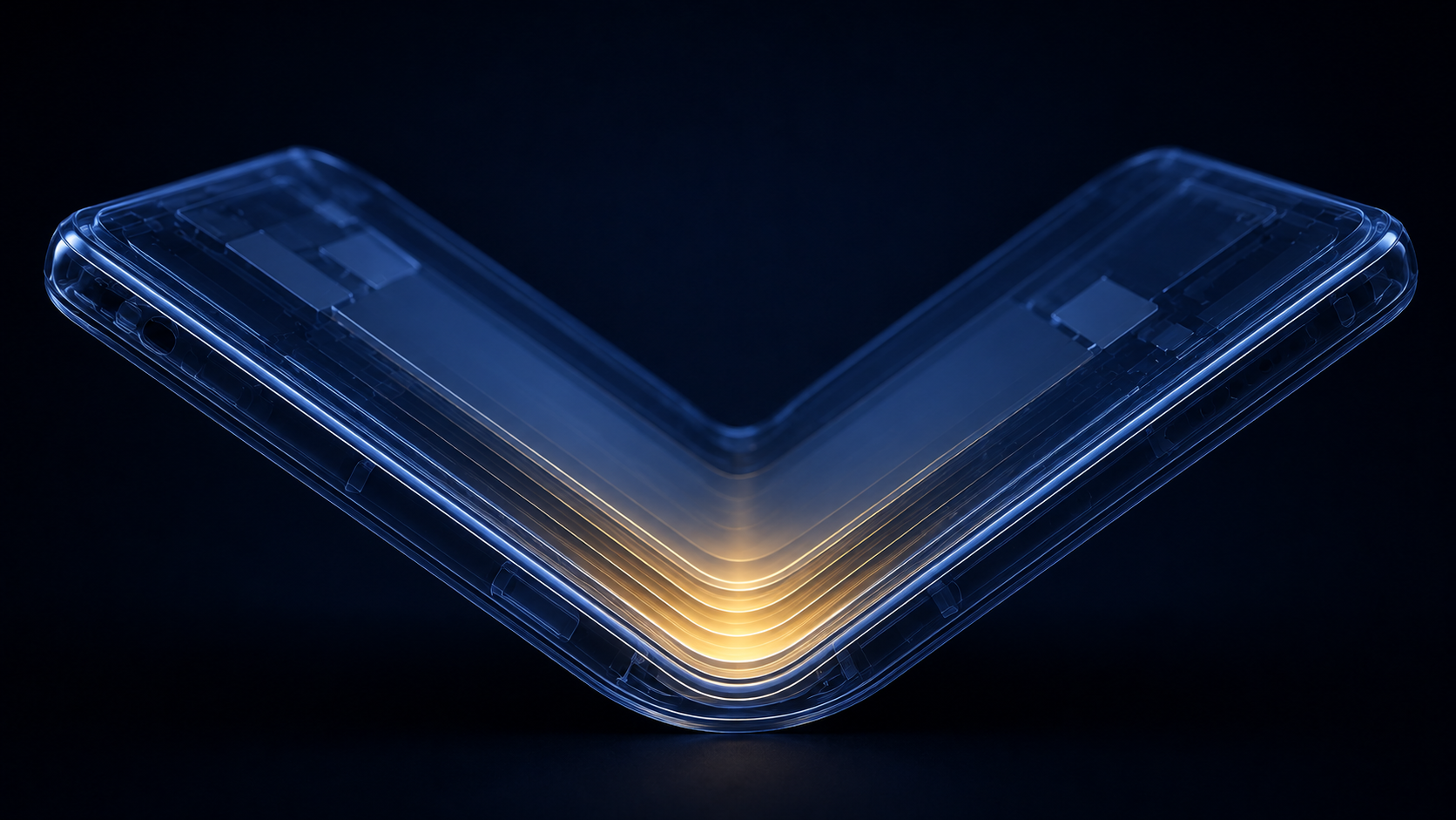
Exploring the Significance of 3D-SOC and 3D-IC in Cutting-Edge 3D Advanced Packaging
As semiconductor manufacturing processes evolve more gradually, 3D packaging emerges as an effective means of prolonging Moore's Law and enhancing the computational prowess of ICs. Within the realm of 3D stacking technology, the Interuniversity Microelectronics Centre (imec) based in Belgium categor...
News

Differences Between 3D-SIP and 3D-SIC: Why Are TSMC, Intel, and Samsung All Actively Involved?
As semiconductor fabrication technologies continue to advance, the number of transistors in integrated circuits (ICs) has steadily increased. Initially, ICs contained only tens of transistors, but as technology progressed, ICs integrating hundreds of thousands of transistors enabled the realization ...
- Page 1
- 2 page(s)
- 7 result(s)